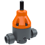
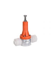
Pressure Relief Valve DV718


• For constant working pressures
• Low vibration, pressure spike control
• Easy adjustment of the pressure, also during operation
•100% free of back-pressure in the rest position
• Diameters from DN8 to DN100
• PVC, PP and PVDF materials
• PTFE membrane
Adjustment range: 0,5 – 10,0 barFeatures
• Stable control behaviour and low vibration • Low maintenance • Low pressure rise up to full valve opening • Friction-free components • Absolutely leak-tight due to flat diaphragm with chambers • For viscous fluids and fluids containing solids • ATEX-approved Aplications
• Chemical plant construction • Industrial plant construction • Water treatment • Galvanotechnics • Galvanic engineering Use
• Controlled directly by the medium, the pressure sustaining valve is used in industrial plants to stabilise the preset working pressures on the primary side. • In order to avoid pressure peaks, the pressure maintaining valve can also be used as a relief valve. For this purpose, the pressure maintaining valve is installed in a bypass line. Valve functions
• The ribbed diaphragm, sized for the full valve stroke, separates the fluid in the valve body from the upper part and the atmosphere. The hermetic seal • especially in the higher temperature range – is ensured by moulded sealing rings. – In the closed rest position, the diaphragm under the valve seat is only loaded with a low secondary pressure. If the working or primary pressure rises, the diaphragm is lifted against the spring force. The valve opens and the pressure is reduced. The flat diaphragm, dimensioned for the maximum valve travel (D/4), reliably separates the medium from the upper side. Valve adjustment
• To read the set pressure, we recommend installing a diaphragm isolating pressure transmitter with pressure gauge in the primary line. • 1. Remove the protective cap (DN 10 – DN 50). • 2. Loosen the lock nut on the adjusting screw. • 3. Turn the adjusting screw clockwise (pressure increase) until the desired set pressure or opening pressure is reached. Fluids
• Neutral and aggressive liquid fluids with elements containing solids if the valve components in contact with the fluids are resistant to the operating temperature according to the Divatec resistance list. • In the case of nitric acid or sulfuric acid, ask us about the exact conditions of use.
More Specifications
Temperature of the medium • see pressure-temperature diagram Operating pressure • See pressure-temperature diagrama Adjustment range • DN 8: de 0,5 a 10 bar • DN 10 – DN 50: de 0,5 a 8 bar Nominal Pressure (H2O, 20°C) • PN 10 Working pressure • Equal set pressure plus flow-dependent pressure increase (see characteristic curves). Opening pressure • DN 8: 0,5 bar • DN 10 – 50: 0,3 bar Hysteresis • ≤ 0,5 bar Flow body valve • DN 8: PVC-U, PP o PVDF • DN 10 – 50: PVC-U, PP or stainless steel V4A Upper part • PP, glass-fibre reinforced Membrane • PTFE (EPDM membrane, PTFE coated on the fluid side) O-rings • – • FPM • EPDM Screws • Stainless steel (1.4301) Control• Fluid-operated


Follow Us!